|
Rebel Fork Framework
|
Radians and degrees are two units of measurement for angles. A full circle is 360 degrees, while the same angle in radians is 2π. This means that 1 radian is equal to 180/π degrees, and 1 degree is equal to π/180 radians.
To convert an angle from degrees to radians, you can use the following formula:
To convert an angle from radians to degrees, you can use the following formula:
The Atan2 function is a two-argument arctangent function that calculates the angle between the positive x-axis and the ray from the origin to the point (x, y) in the Cartesian plane. The result is given in degrees and is confined to the range (-180, 180].
The yaw angle is the angle between the positive x-axis and the projection of the direction vector onto the x-z plane. You can calculate the yaw angle from a direction vector using the Atan2 function as follows:
Some Atan2 result values for reference:
Here is a C++ function that clamps an angle value in degrees between -180 and 180 degrees:
This function takes an angle value in degrees as an input and returns the clamped angle value between -180 and 180 degrees. The Urho3D::Mod function is used to calculate the remainder of the division of the angle by 360, which brings the angle value within the range of -360 to 360 degrees. Then, if the angle is greater than 180 degrees, 360 is subtracted from it to bring it within the desired range. Similarly, if the angle is less than -180 degrees, 360 is added to it to bring it within the desired range.
This clamping function is very useful when you add or subtract angles. It is not absolutely necessary but makes this easier to understand and also keeps value close to 0 for better precision.
Linear Interpolation (Lerp) is a mathematical function that is used to find a point some fraction of the way along a line between two endpoints. In other words, it is used to find a value between two values that are known.
An easing function is a mathematical function that modifies the time value of an animation to create a more natural and smooth effect. It is used to change the rate of change of a parameter over time. Easing functions are mostly used in animations to change a component value in a defined period of time. You can move objects, change their colors, scales, rotations and anything you want simply using easing equations.
For example, if you have an animation that moves an object from point A to point B in a straight line, it will look very robotic and unnatural. But if you use an easing function to modify the time value of the animation, you can create a more natural and smooth effect.
There are many different types of easing functions, each with its own unique effect. Some common types include linear easing, quadratic easing, cubic easing, and elastic easing.
Here is an example of interpolation with easing:
To convert one vector to another use the .To*Vector* operators. Here are few examples:
To rotate vector by quaternion use the following:
To transform vector with matrix use multiplication:
If you use Matrix3x4 or Matrix4 but you only need to apply rotation and scale you can add a zero as W component and use multiplication:
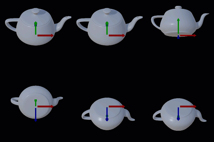
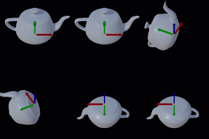
All rotations in the engine performed in a clockwise order. Here is what going to happen with a vector {x,y,z} if rotated around an axis at 90 degrees:
In the engine, matrices are column-major (like in OpenGL) while in DirectX they are row-major.
In general, for a column-vector on the right (OpenGL convention), M1 * (M2 * (M3 * v)) = (M1 M2 M3) * v, i.e. the left-most matrix is at the root node while the right-most is at the leaf node.
When you apply multiple transformations (like translation, rotation, and scaling) to an object, the order in which you multiply the matrices matters. The general order is:
This order ensures that each transformation is applied correctly without unintended distortions. For example, if you scale an object first, then rotate it, the rotation will not affect the scale. Similarly, translating an object after scaling and rotating it ensures that the object moves to the correct position.
To visualize how matrices are applied to object transformations, you can think of it as a series of steps:
In the engine, this sequence is represented by multiplying the matrices in the reverse order of how you want the transformations to be applied. For example, if you want to scale, then rotate, and finally translate an object, you would multiply the translation matrix by the rotation matrix, and then by the scaling matrix.
Below is a sample code demonstrating the order of matrix multiplication:
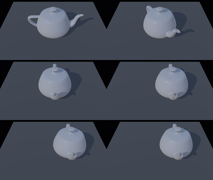
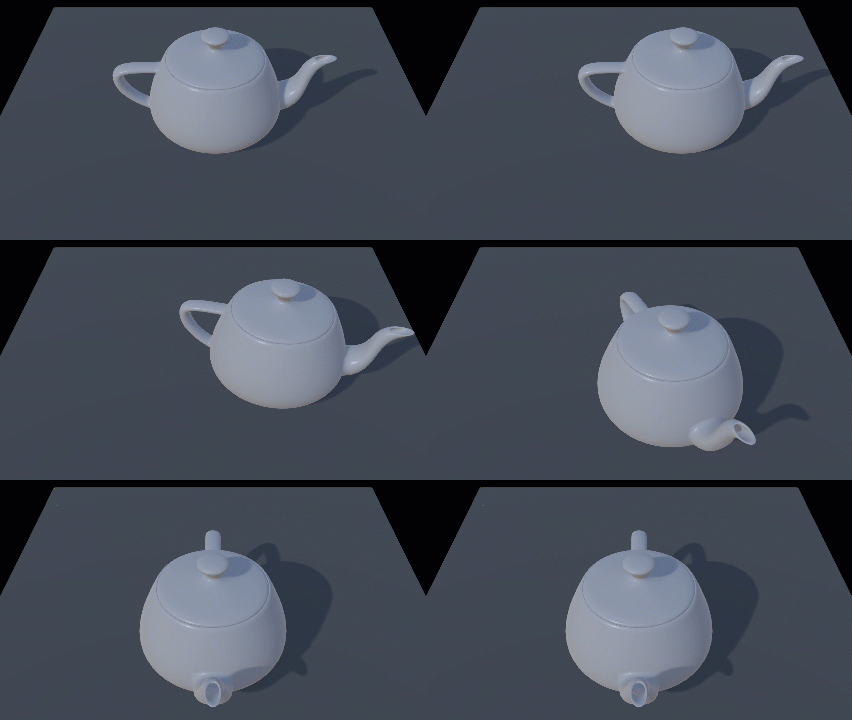
Alternatively, if you prefer a visual approach, here are some illustrations depicting the matrix multiplication sequence:


To combine world transform matrices to make a matrix that would transform from one game object space into another object space, you can multiply the inverse of the world transform matrix of the second object by the world transform matrix of the first object. This will give you a matrix that will transform from one object space to another object space.
Here is an example code:
The transformAtoB matrix will now transform from the nodeA object’s space to the nodeB object’s space.
The bind pose matrix is the matrix that represents the position and orientation of a joint in its default pose. It is used as a reference for skinning, which is the process of deforming a mesh based on the movement of joints in a skeleton.
When an animation is played, each joint in the skeleton is transformed by its animation matrix. The bind pose matrix is then used to transform the vertices of the mesh into the space of the joint. This is done by multiplying each vertex by the inverse of the bind pose matrix for the joint it is associated with.
To build a quaternion that rotates an object by 180 degrees around each axis (X, Y, and Z), you can use the axis-angle representation of quaternions. Here’s how you can do it:


Quaternion multiplication order is the same as with matrices. Here is an example to illustrate it:
To reverse rotation take result of the Inverse() method: